Creating Tie Configurations
To create a tie configuration:
- From Estimating, Order Entry, or CAD/Detailing, click Tools , then select Tie Designer on the Left Menu.
or
From the Order Entry Takeoff Tools menu, select Tie Designer.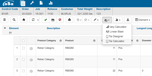
The Tie Designer screen displays. - Verify or update the Building Code associated with the tie configuration.
- In the Tie Pattern field, enter a unique ID for your tie pattern.
HINT: To edit an existing tie pattern, enter its ID, choose from the drop-down list or use the tie pattern palette. - Complete the setup fields described in Tie Designer Screen Overview.
In general, the setup fields determine at what level the configuration is saved. For example, a configuration saved for a specific job can only be use for that job. - Select your configuration shape: rectangular or circular.
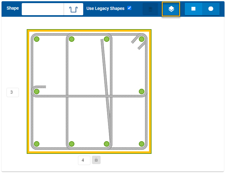
- In the drawing area, use the Vertical Point controls to set the number of vertical bars in each side of the column or beam.
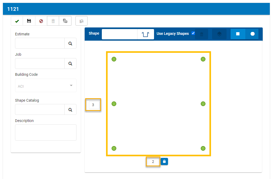
For circular configurations, simply select the number of verticals in the column. - Add shapes to the configuration:
- In the Shape field, select the desired shape.
- In the drawing area, click a vertical point to start the shape.
- Click additional points to draw the shape. Your stirrup or tie will wrap around each vertical bar that you click.
- Repeat to add additional shapes.
- Click Finish
 .
.
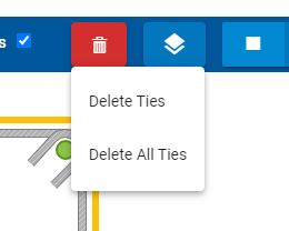
To delete ties from the configuration:
- Click Delete
 .
.
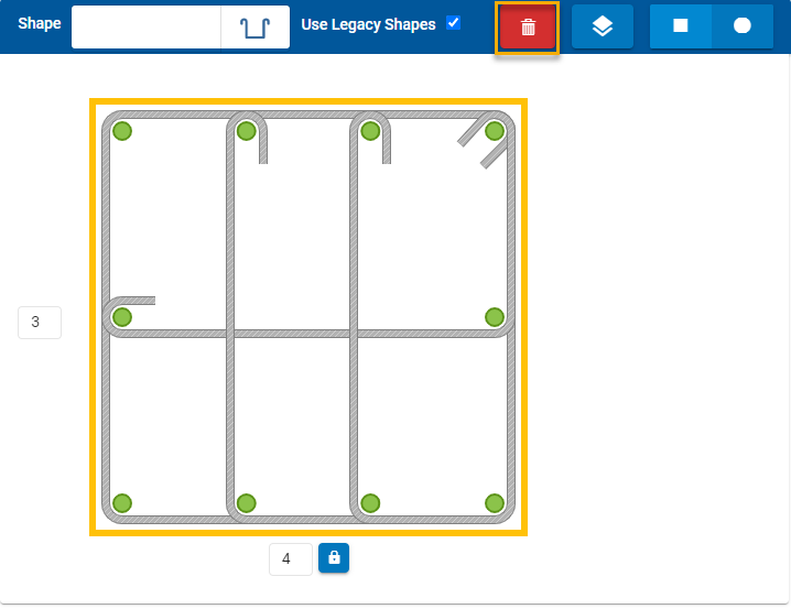
- Select Delete Ties.
Click on the tie to be removed.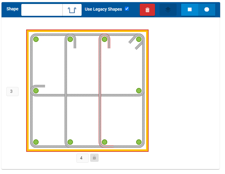
To delete all ties in the configuration:
- Click Delete and select Delete All Ties.
A warning prompt displays.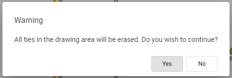
- Click Yes.
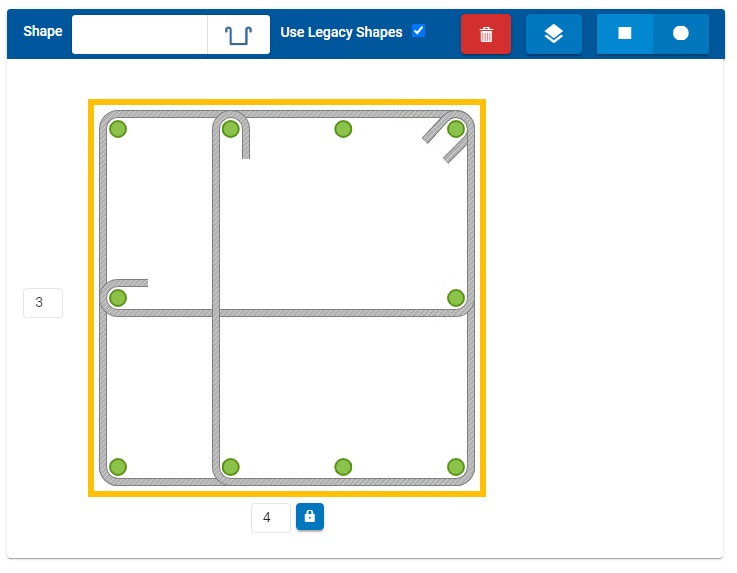
To specify the level at which the configuration is drawn in aSa CAD/Detailing:
- Click Layers
 .
.
- Click on the tie that is to be adjusted
- Set the layer where the tie should be placed.
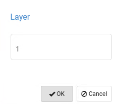
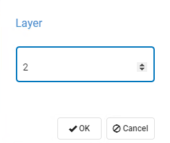
- Click OK.